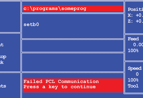
If the CNC control 'hangs' on a command to the PLC, and displays the error "Failed PLC Communications..." after pressing the Esc key, you may need to run PORTTEST to determine the cause of the problem.
- First, verify that you have power to the PLC.
- Next, check all cables between the CNC and the PLC.
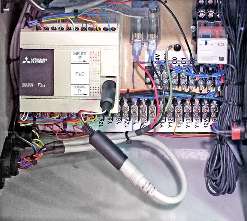
- Then, unplug and replug the connectors to and from the RS422 converter in the CNC, and the DIN connector at the PLC.
If you have power and the connections are good, and you unplugged and replugged the cables, the next step is to run PORTTEST.
PORTTEST is a simple app installed on the OmniTurn to test the communication port that the CNC uses to 'talk' to the PLC.
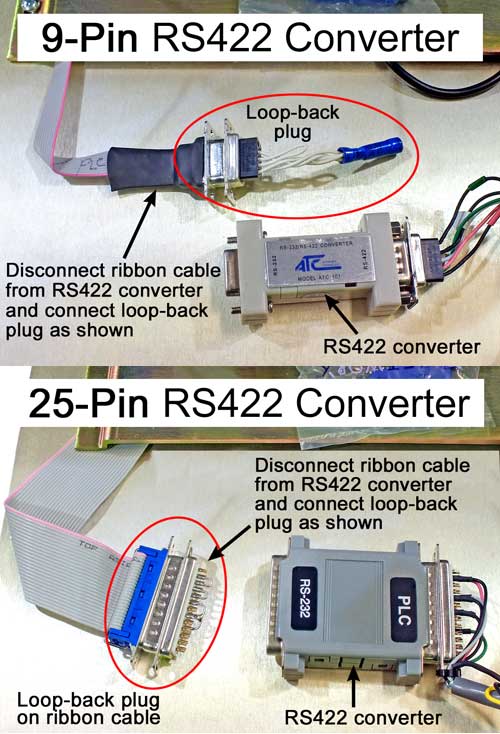
- With CNC power off, first disconnect the cable to the PLC at the CNC and a connect the RS422 loop‑back connector.
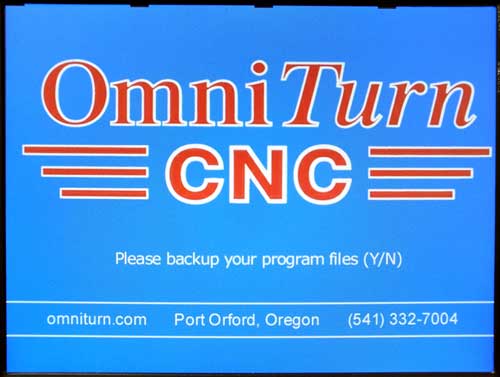
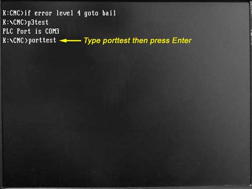
- Power up the CNC and drop to DOS.
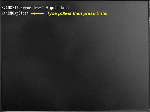
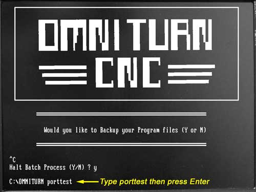
- At the K:\CNC prompt type PORTTEST, then press Enter.
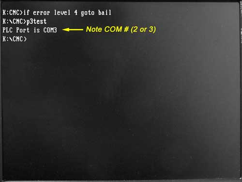
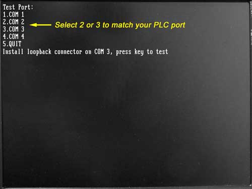
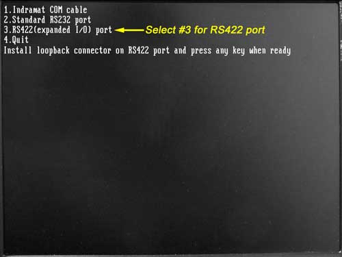
- Press the number that corresponds to the port your PLC is connected to (either COM2 or COM3 depending on motherboard), then press any key.
NOTE: G3 PORTTEST choices are different: select 3.RS422(expanded I/O) port - The test will respond COMx is OK or Waiting for response, then Test failed.(On G3 CNC the prompt sticks at "Waiting for response"; this means test fails. Press Esc key to continue).
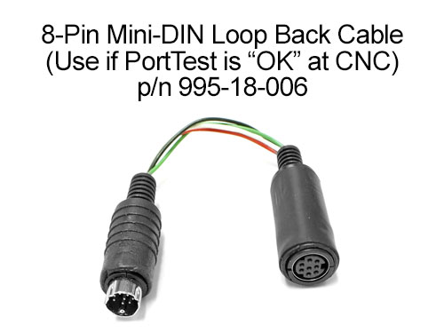
- If the port is OK, carefully examine the cable between CNC and mini DIN connector at PLC. Use the a Mini‑DIN loop‑back connector to run PORTTEST at the PLC DIN connector. Or ring out cables according to this wiring diagram.
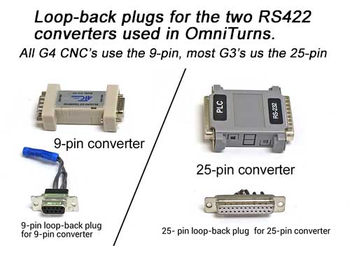
If the port fails, run PORTTEST at the motherboard using the 9 or 25 pin loop‑back connectors that shipped with the PLC or loader. Set the CNC power off, disconnect the ribbon cable that is attached to the RS422 converter, put the loop‑back connector on the ribbon cable and run PORTTEST again.
Below are illustrations and captions describing the entire process.

(These are G4 CNC screens; for G3 screens click here)
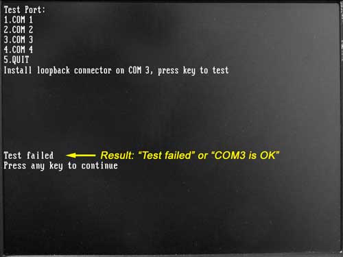
The results will be "Test failed" or "COM3 (or COM2) is OK".
If failed, the next step is to repeat the PORTTEST at the input of the RS422 converter to see if that's the culprit.
If OK, the next step is to repeat the PORTTEST at the input of the PLC using the Mini‑DIN loop‑back connector.
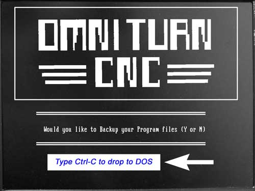
G3 CNC: When the control boots up to the File Backup prompt, press Ctrl-C instead of y or n and you will drop to the DOS prompt, which will be C:\OMNITURN_
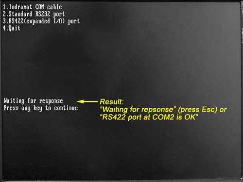
If waiting, press Esc key. The next step is to repeat the PORTTEST at the input of the RS422 converter to see if that's the culprit.
If OK, the next step is to repeat the PORTTEST at the input of the PLC using the Mini‑DIN loop‑back connector.
Click here to go back to the instructions for G4 CNC.
Click here to go back to the instructions for G3 CNC.
If the Test passes, then the motherboard/ribbon cable connection is good, and the converter may have failed.Reconnect the ribbon cable and repeat PORTTEST at the PLC connector on the rear panel; if the test fails, replace the converter: 9-pin or 25-pin
If it passes this time, the issue was solved by disconnecting and reconnecting cables.
If the Mini‑DIN loop-back connector is not available, carefully examine the cable between CNC and mini‑DIN connector at PLC. This wiring diagram shows pin numbers to ring out.
Power down the CNC and disconnect the mini‑DIN connector from the PLC and plug it into the female loop‑back plug. Plug the male end of the loop‑back connector into the PLC.
Power up the CNC, drop to DOS and run PORTTEST as before. If necessary, go back to the instructions for G4 CNC, or G3 CNC.
If the test passes, then the cables are good, and the PLC may have failed. Power down the CNC. Remove the loop‑back connector and reconnect the DIN cable, and see if you can communicate with the PLC. If so, disconnecting and reconnecting the cables solved the problem; if not the PLC is probably bad.