The Rexroth “RM” and newer “RTC” rodless cylinders used on the OmniTurn ZipLoader are designed to operate for many hundreds of thousands cycles. We have customers who have run up to a million cycles before replacing the cylinder. Because Rexroth discontinued the RM series rodless cylinder and replaced it with the RTC series, replacing the older RM rodless cylinder involves changing hardware and rewiring the four sensors on the cylinder.
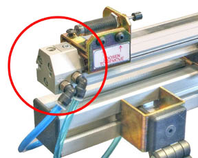
Two versions of the RM‑equipped ZipLoader were shipped, as illustrated below. The earliest version mounted the rodless cylinder on an aluminum plate; the later version used brackets that mounted directly to the frame extrusion.
REPLACING OLDEST‑STYLE RM:
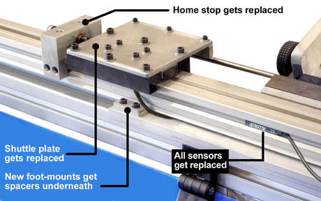
- The home stop, mounting feet and shuttle plate get replaced when replacing rodless cylinder on oldest ZipLoaders.
-
- New RTC rodless cylinder mounts on the plate using new mounting feet. Spacer‑plates that fit under the new feet are provided to put cylinder at proper height. The RTC cylinder is stiffer, so only two mounting feet are required.
-
- Replace shuttle assembly; see illustration below for details regarding shuttle plate alignment.
-
- All four sensors on rodless cylinder also replaced. The new sensors have three wires; the old ones only two. See PLC pages for wiring information.
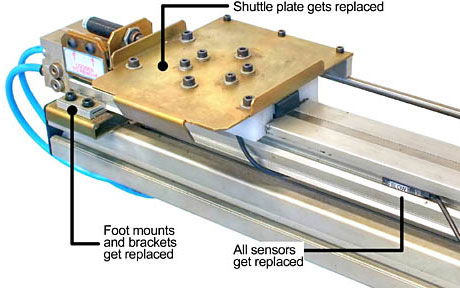
REPLACING NEWER‑STYLE RM:
- Shuttle plate and foot mounts get replaced.
-
- New, higher, foot mount brackets are provided. The RTC cylinder is stiffer, so only two mounting feet are required. Position the brackets so they are about ten inches from each end of the rodless cylinder.
-
- Replace shuttle assembly; see illustration below for details regarding shuttle plate alignment.
-
- All four sensors on rodless cylinder also replaced. The new sensors have three wires; the old ones only two. See PLC pages for wiring information.
ALIGNING THE RODLESS CYLINDER
After replacing the rodless cylinder, the shuttle assembly and rodless cylinder must be aligned with the ‘vee’. To properly align the shuttle assembly, it is best to use a plain ¼″ pushrod (p/n 790‑02‑017) which will lay flat in the vee.
- First verify that the rodless cylinder is parallel to the ‘vee’ front within about 1/32″.
-
- A 6” scale is adequate; measure from one edge of the band on top of the cylinder to the edge of the Vee Front at two places about 24″ apart.
-
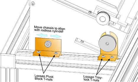
- If the cylinder is not parallel to the chassis, loosen the Pivot Block and Tray Lock Block on one side (shown at left), and move the chassis assembly to make it parallel with the rodless cylinder.
-
- The blocks are held in place with t‑nuts.
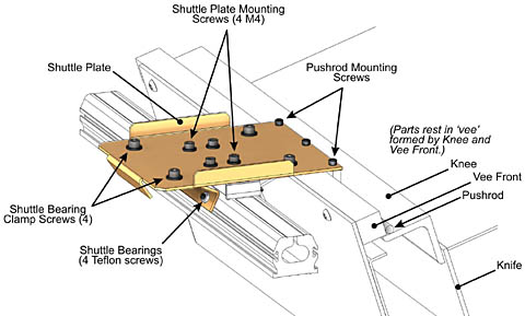
- After making the chassis parallel to the rodless cylinder, the shuttle plate assembly must be aligned to the vee. There are 11 screws in the top of the shuttle assembly: (shown at right)
-
- The four middle ones are M4 screws which hold the plate to the shuttle.
-
- The two rows of two on either side of the four are 10‑32 which attach the slide bearings.
-
- The three 6‑32 on the far end attach the push-rod to the plate. To align the assembly, first loosen all these screws.

