 The Oregon Coast to show picture; click anywhere else (Apple IOS: refresh page) to hide picture.
NOTE: Click on brown textThe Oregon Coast to show picture; click anywhere else (Apple IOS: refresh page) to hide picture.
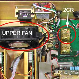 Located in CNC toward back panel..
How it works:
The motherboard turns on the computer power supply when the Control On button is pressed. The computer power supply turns on relay 2CR, which connects 110 VAC line voltage to the upper fan (and to the servo and auxiliary power supplies).
For reference, front panel wiring schematic PDF is available here.
Possible causes:
Troubleshooting steps:
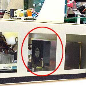 Lower Fan (located on lower chassis)is running. If you prefer to use a meter, check for 12 volts DC between black and yellow wires of any spare computer power supply connector
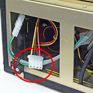 Computer power supply connector..
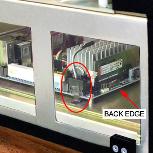 Power supply enable cable.from "Control On" switch is connected at motherboard. Note: on some motherboards, this connector is located on back edge of motherboard instead of side.
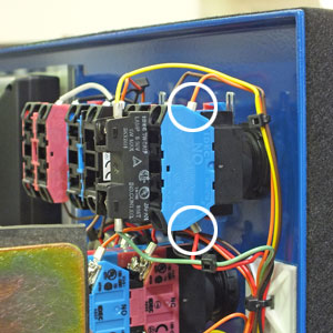 Control ON switch contacts. on the Control On switch: you should measure about 3.5VDC.
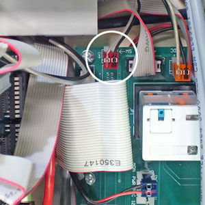 CN9 PWR SW on connect card.connector on the connect card
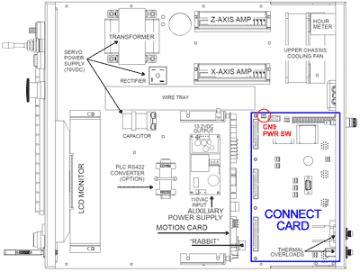 Connect card showing PWR SW location.. Measure across the black and white wires.
Power supply enable cable. at the motherboard.
Connect card showing PWR SW location.. Measure across the black and white wires.
Power supply enable cable. at the motherboard.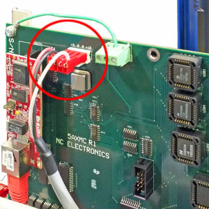 CN304 on 5AX card., located at the top of the 5AX card, on the back-side. Verify that it is securely plugged in, then use volt meter to verify 12 volts DC between black and white wires.
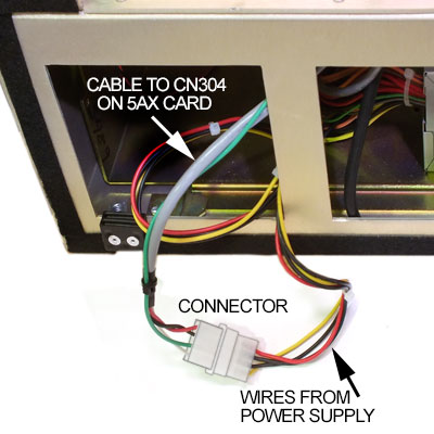 CN304 cable to power supply. is connected to the power supply.
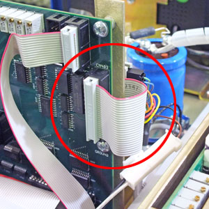 CN403 to front panel connect card. on the inside edge of the 5AX card and verify that it is securely plugged in. Unplug and replug to verify connection. The other end of this CN403 ribbon cable is connected to front panel connect card. The 12 volt line is routed from the front panel connect card via CN1. These two connectors are not easily accessible without removing the front panel, but they can be seen
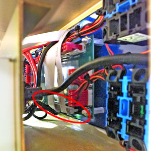 CN403 and CN1 at front panel connect card through opening at the side of the control.
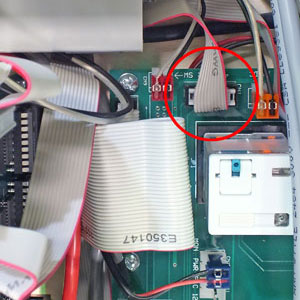 CN1 from front panel connect card. connector on the connect card
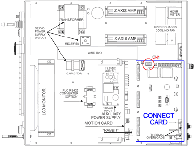 Connect card showing CN1 location. and verify that it is securely plugged in. This is the last connection in the 12 volt string from the computer power supply. If the lower fanLower Fan (located in lower chassis) is working but you don’t have upper fan or 2CR on connect cardLocated in CNC toward back panel. there may be a open trace on circuit card or bad cable.