 The Oregon Coast to show picture; click anywhere else to hide picture (Apple IOS: refresh page).
NOTE: Click on brown textThe Oregon Coast to show picture; click anywhere else to hide picture (Apple IOS: refresh page).
This page addresses a condition where you can jog, but the spindle will not start..
These instructions apply only to inverter drive on legacy spindle panel with TB1 terminal strip.
Most likely cause is open Spindle Off/Auto Switch, or open Palm Box E-Stop switch, or bad connection between these one of these swiches and Connect Card or TB1.
After these tests, if the spindle still does not start, you'll need to check some things inside the spindle drive cabinet:(For reference, here is PDF of spindle cabinet components)
Any time the control is on with the servos on, the leftmost relay in the row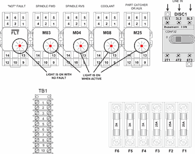 Relays in Spindle Cab at the top of the electrical panel in the spindle drive box must be lit. The relays in the very oldest (pre-1995) spindle drive boxes don't have lights. If your machine is that old, you will need to use a voltmeter to verify relay status: ON = 12VDC betweeen relay contacts 13 and 14; OFF = 0VDC between relay contacts 13 and 14.
The spindle gets its start command through the M03 or M04 relay in the spindle drive box.
The signals come down from the control to the long terminal strip that runs down the left side of the electrical panel (called TB1). Terminal 1 is the top terminal on the strip. If the relays are not turning on (as indicated by the LED lights in the relays), you'll need to check some voltages on that strip. The control and servos need to be on to check these.
Before measuring voltages issue M05 from MDI mode. This is to verify that neither M03 or M04 are engaged.