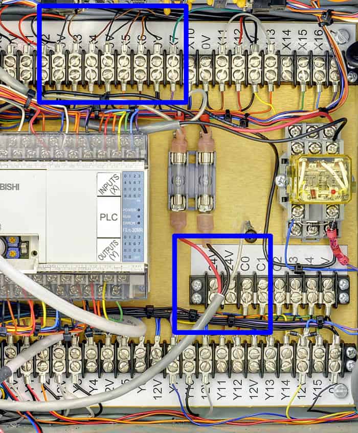
The picture below shows the original sensor wires connected at the top terminal strip.
The black wires from the old sensors get replaced with brown, and the brown wires get replaced with black. The extra blue wires are all connected to the 24V terminals (see next picture).
- New “Home” sensor black wire goes to X3; brown wire to 0V
- New “Slow” sensor black wire goes to X4; brown wire to 0V
- New “EoB/InPlace” sensor black wire goes to X5; brown wire to 0V
- New “Eject” sensor black wire goes to X6; brown wire to 0V

Picture shows old sensors. With new sensors black goes to X’s, brown to 0V’s
The picture below shows the “+24V” screw-terminal, where the extra blue wires from all sensors must be connected. You can put two wires under each of the two screws.

Four blue wires to +24V terminals.