OmniTurn   CNC Lathes Made in Oregon
 Fast... Precise... Affordable... Home Contact

The World’s Most Cost-Effective Turning Machines

Intermittent M12 or M13 (G3 CNC)

These instructions apply only to machines equipped with MAC solenoid valves shipped before 2008.
Intermittent failure to actuate the collet closer with M12 or M13 on machines equipped with MAC solenoid valves shipped before 2008 can be caused by lower than normal computer power supply voltage combined with higher than normal voltage requirement on the MAC valve.

First verify that the indicator light on the MAC valves consistently flash with M12 (upper) and M13 (lower).

This insures that the signal is reliably transmitted from the CNC control to the solenoid valve. If the lights don’t flash then you have a different problem.

Air Pack on GT

Image of Air Pack on GT

Next, test the operation using the push-buttons on the Operator's Station.

If the collet actuates reliably using the push-buttons on the Operator's Station (Palm Box) install an Auxiliary Power Supply Kit (p/n 995-09-004).

Collet Actuator Buttons

Image of Palm Box

If collet doesn't actuate reliable from the Operator's Station:

If the collet does not actuate reliably with the Palm Box, but the lights on the MAC valve light, the problem could be mechanical, either in the collet closer or the MAC valve.

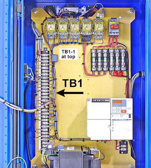
To verify that the voltage is good, open the spindle electronics cabinet and power up the machine.

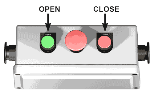
With servos on, and DC voltmeter leads on TB1-12 and TB1-13, meter should read at least 11 volts when collet open button is pressed. Move leads to TB1-14 and TB1-15: meter should read at least 11 volts when collet close button is pressed.

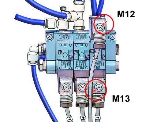
If the voltages are correct, and the lights on the MAC valves light, but the collet doesn’t actuate, the issue could be mechanical.

TB1 Terminal Strip

Image of Palm Box

If the problem persists after installing the auxiliary power supply, it may be caused by faulty driver on motion card, or faulty relay on connect card.

First verify the auxiliary power supply is installed correctly: with servos on, put DC voltmeter leads on TB1-12 and TB1-13. Meter should read about 13 volts when collet open button is pressed. If the voltage is about 11 volts, go back to auxiliary power supply install instructions and correct the issue.


If the voltage is about 13 volts, swap 1CR on connect card with M08 in spindle cabinet.

1CR on Connect Card

Image of 1CR (Servos Enable relay)

M08 on Spindle Panel

Image of M08 (Coolant On relay)

If the problem persists after swapping 1CR with M08, it may be caused by faulty driver on the motion card:

To verify, write a program with eight M13’s then one G04F2 then M30. Run this program in cycle repeat with the spindle cabinet open.

Put meter leads across TB1-12 and TB1-13; meter should read 11.5 volts for two seconds, then zero volts for two seconds as program cycles. If the voltage is 10 volts or less, the driver on the motion card (MC2) is the culprit. Replace U17 (ULN2803; available at DigiKey.com).

U17 on MC2 card

Image of U17 on MC2 card