The programming details for plane switching are not yet finalized, so currently plane-switching commands need to be hidden from the error checking software by placing them in parentheses. The only commands permitted in the plane-switched part of the program are axis moves and feedrate commands. There is no cutter compensation, so it is up to you to write the program for the endmill you are using. All dimensions in the plane-switched mode are in absolute coordinates.
The commands are as follows:
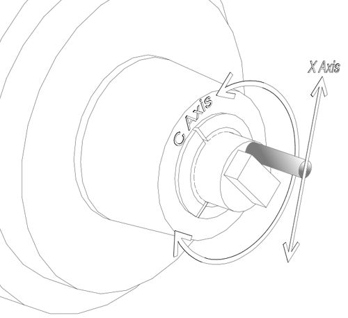
(~PLXC): Start XC mode. The tilde character “~” in a (comment) alerts the Omniturn’s parsing program to scan for a plane switching command.
(~PLZC): Start ZC mode. The tilde character “~” in a (comment) alerts the Omniturn’s parsing program to scan for a plane switching command.
(Xnn): moves the X axis to the specified coordinate.
(Ynn): moves the Y axis to the specified coordinate.
(G02XnnYnnInnJnn): moves X and Y to the specified coordinates clockwise along a circular path with its center located at the I dimension in X and the J dimension in Y.
(G03): same as G02 but travels CCW along the arc.
(Fnnn): feedrate specified in inches per minute
(Znn): moves the virtual mill’s Z axis.
In the ZC plane, the Z dimension is specified as the diameter of the cylinder the tool’s tip would touch.
In the XC plane, the Z axis is the same as it would be if plane switching was not in effect
(Dnn) (ZC plane only): specifies the part diameter at which the Y dimensions are translated to C axis rotation. This value defaults to the virtual mill’s Z position (that is, the diameter at the tool’s tip) at the start of the plane-switched operation. It should only be changed when the Y position is 0, since it causes a re-scaling of the Y dimensions on the first move after it is programmed. The reason this parameter exists is that you may want the Y dimensions to be calculated at the surface of the part rather than at the depth of cut.
(END): cancel plane-switch mode.
Note: If you copy the plane-switch programs, do not include comments in the plane switched section. Nothing is allowed in the plane-switched program except the program statements described above.