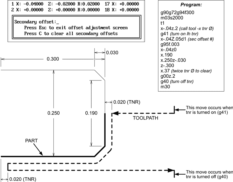
The tool nose radius and the amount of offset is entered into the Secondary Offsets Table. Press F9 in Auto Mode to access the table.
An excerpt from the Secondary Offesets Table is illustrated below, along with an example program and toolpath.
In the Secondary Tool Offset Table:
Left or right compensation is determined by viewing the toolpath from the cutter's point of view. The tool is moved away from the part to accommodate the tool nose radius (see illustration below):
A simple OD part is illustrated below, using the same cutter on both sides of part, cutting both toward and away from the spindle.
The canned cycle (g41 or g42) creates a toolpath that follows the contour of the part, offset by the "R" value set in the Secondary Offset Table.To put the centerline of the tool nose radius on that toolpath, the program applies the "X" and "Z" values:
The sign (plus or minus) of the "X" and "Z" values is to move the tool toward the part the amount of the TNR.