Tooling Plate at Machine Home
This page contains general information about setting tool offsets.
This information is also available as printable PDF here.
Tool offsets locate the cutting tools relative to the part.
The start up process of every CNC machine includes "establishing home". Home is machine zero, that is, x0z0. This is also "T0".
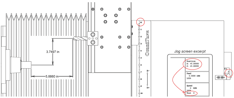
When the tooling plate is at home, the cutting edge of each tool is at machine zero. The illustration below uses a single tool, a drill bit, to illustrate offsets. With the machine at home, the position indicator displays X:0.00000; Z:0.00000, and T0 as the tool number.
Tooling Plate at Machine Home
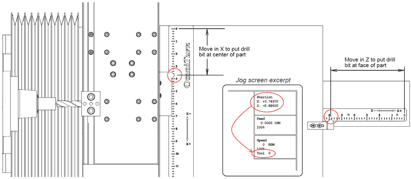
Without an offset, when a tool, a drill bit for example, is moved to a the center of the part, at the face, the position indicator displays the location of the tool relative to machine zero, say x3.74970 z-5.88600. (These are arbitrary numbers, depending where on the tooling plate the drill bit is located). The position indicator also displays “T0”.
Tool Located Relative to Machine Home
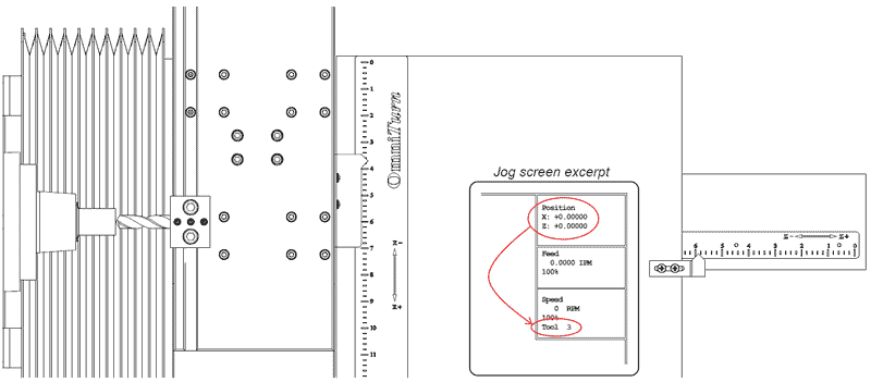
When the offset for that drill bit has been established, and the tool, now called T3, for example, is moved to the center of the part, at the face, the position indicator displays the location of the tool relative to the part: X:0.00000; Z:0.00000. The indicator also displays Tool 3.
Tool Located Relative to Part (X0Z0)
When the program is written, each tool is assigned a number, from 1 to 31. A tool is called by simply typing the tool number on a line by itself. In the case of the example drill bit, T3.
To reduce cycle time, tools are moved into position (called) at rapid speed (g00). The position must be greater than about 0.020” from the part itself because there is some overshoot due to fast decelleration. For this example, the drill bit will be called to the center of the part (X0), 0.100” from the face (Z.1), then peck-drill a 1/2” deep hole:
Initial setting of offsets is done in Jog mode, by taking light cuts or using shims, etc. After measuring the first part, the offsets can be adjusted as required to meet the print.
Procedures for setting four commonly used tools are described below.
A one inch diameter blank will be used for the examples.
After setting the offsets, the center of the part will be X0, and the face of the part will be Z0. If the tool and tool holder is not moved, only the Z offset needs to be reset for difrerent length parts; X0 will remain at the center for each tool. Calling that tool in another part program will put it on center for that part as well; only the Z offset needs to be set if length of part is different.
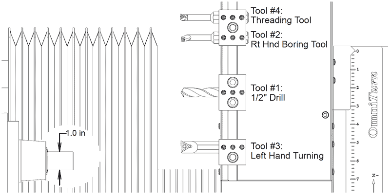
Tooling Plate with Various Common Tools
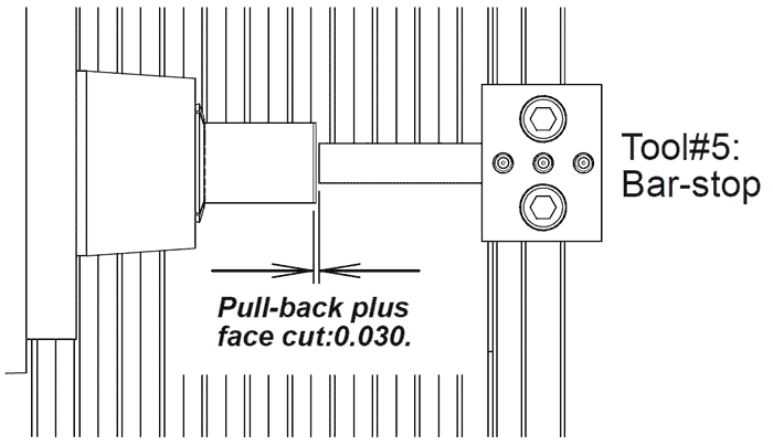
For bar jobs, the bar-stop offset must be set first. Locate the bar-stop as required for the length of part. Feed the bar to stop against the stop, then close the collet. The Z location of the stop is the distance from the finished face plus the pull-back, if not using a dead-length collet. For this example that will be 0.030”, estimating 0.01” pull-back, and knowing 0.020” material to be removed.
Tooling Plate with Bar Stop at Face of Bar
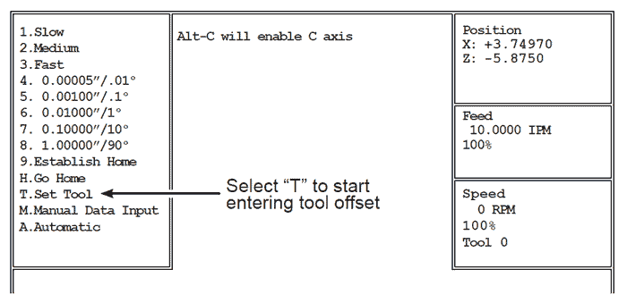
1. Press ‘T’ on the jog screen
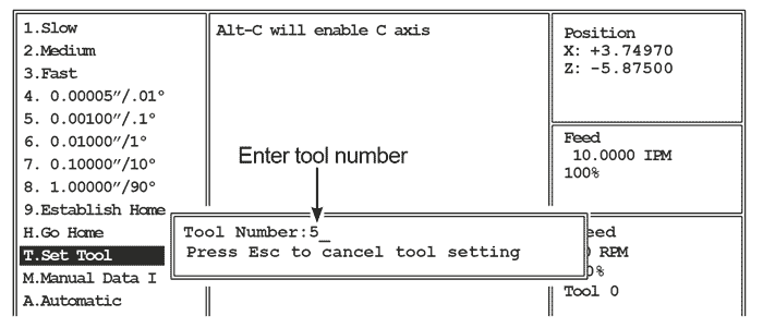
2. Press ‘5’ for Tool Number
3. Press ‘Z’ for Z-axis
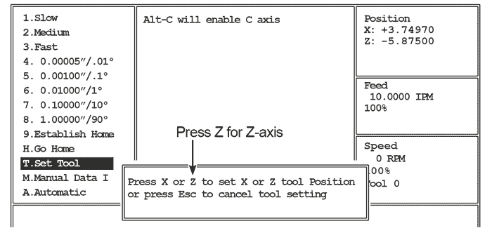
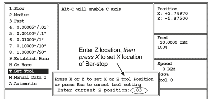
4. Enter the Z location, then press X to enter the X location. NOTE: This is a ‘shortcut’, especially useful for the bar-stop, when the location of the tool in X and Z are both known.
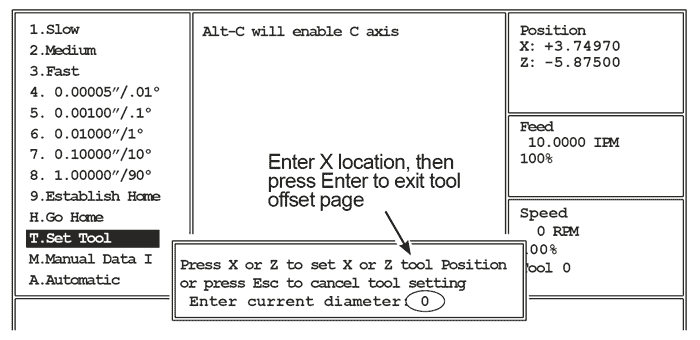
5. Enter the X location, then press Enter to exit tool offset page. NOTE: For this bar-stop example, a diameter value of 0 was selected, but the X location can be set for whatever diameter the job requires.
The Z-axis offset establishes the face of the part. Setting it depends on the the type of job, bar or blank; if blank, whether it’s finished or unfinished.
If it’s a bar job, you’ve already set the offset for the bar-stop (T5, above), so it’s just a question of how much material you want to take off the face. Jog in Z to that location, and take a face cut: this will be Z0 for the part.
Tooling Plate with Left-hand Turning Tool at Face of Bar
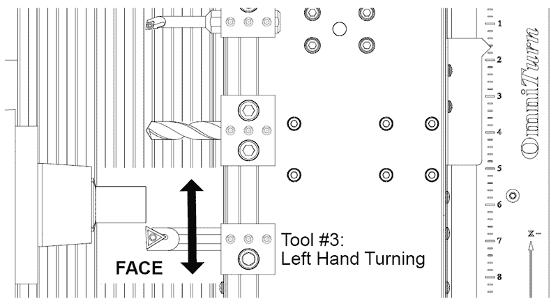
If it’s a part job and you’re using a blank (unfinished part), before you put the part in the collet measure how much you have to make the part to size. Then touch off on the face of the blank; for this example that will be Z0.020. Set Z location to .02.
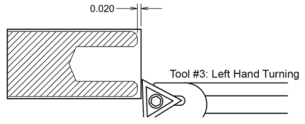
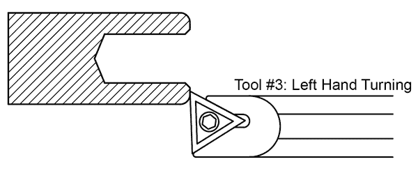
If it’s a part job and you’re using a finished part, touch off on the face of the finished part; that will be Z0. Set Z location to 0. The offsets can be easily adjusted later, to 1/10 increments, so “close” is good enough for now.
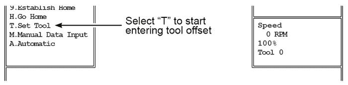
1. Press ‘T’ on the jog screen
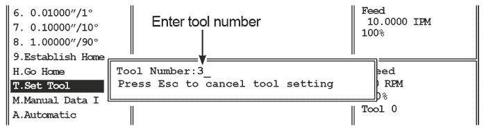
2. Press ‘3’ for Tool Number
3. Press ‘Z’ for Z-axis
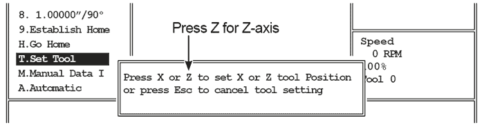
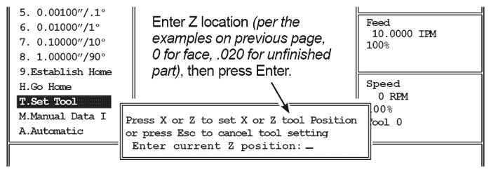
4. Enter Z location:
For the bar-job example, and for the finished part example the location is 0.
For the unfinished part example, the location is .02.
Press Enter to exit Tool Offset page.
There is no need to be absolutely precise at this point because the offset can be easily adjusted by tenths later on.
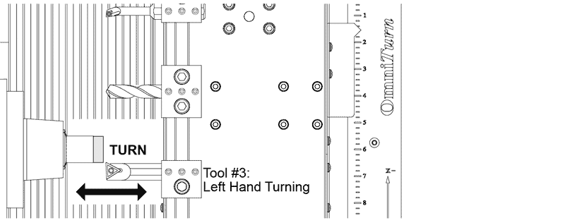
The X-axis offset establishes the diameter of the part. Power up the OmniTurn, turn on servos, establish home. From MDI mode command M03 and some speed appropriate for the material. Jog tool to just touch the diameter, then jog away from the part in Z. Use incremental jog to move into the part sufficient to take a skim cut (0.005 or 0.010). This cut will be used to establish the X offset.
Tooling Plate with Left-hand Turning Tool at Diameter
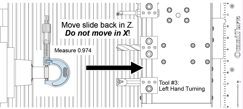
After jogging in to make the skim cut, jog away from the part enough to get a micrometer on it. Do not move the slide in X axis!
Measure the diameter. This value will be used to establish the X offset.
Measure Turned Diameter
1. Press ‘T’ on the jog screen
2. Press ‘3’ for Tool Number
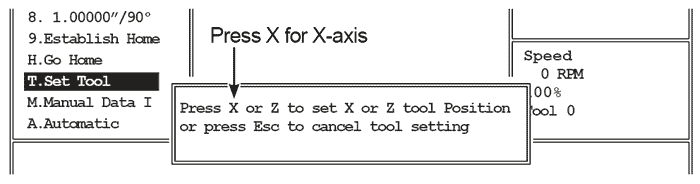
3. Press ‘X’ for X-axis
4. Enter measured diameter of blank,then press Enter.
There is no need to be absolutely precise at this point because the offset can be easily adjusted by tenths later on.
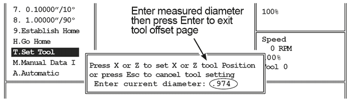
NOTE: for a right-hand turning tool cutting on the back-side, the diameter will be entered as a minus: -.974.
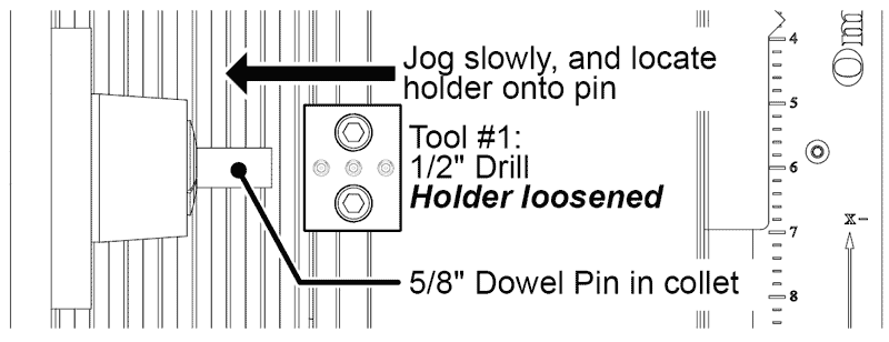
There are two ways to set the X offset for a drill:
Set Offset for Drill using Pin in Collet
Set Offset for Drill using Known Diameter
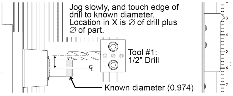
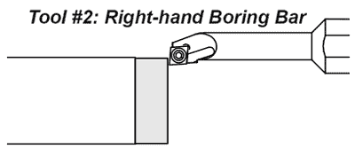
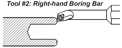
If you are using the original blank in the collet from the turning tool example, touch off on the known diameter (0.974). The offset in this case is minus, so press ‘T’ to start the offset process; then ‘2’ for tool 2, then -.974 for current diameter. If you are taking a skim cut on a new blank, measure the turned diameter, then enter that value, as a minus.
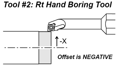
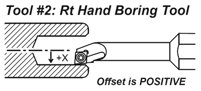
If you are using a finished part, touch off on the known inner diameter. The offset in this case is plus, so press ‘T’ to start the offset process; then ‘2’ for tool 2, then enter the ID as a plus.
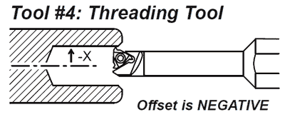
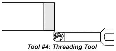
If you are using the original blank in the collet from the turning tool example, touch off on the known diameter (0.974). The offset in this case is plus, so press ‘T’ to start the offset process; then ‘4’ for tool 4, then -.974 for current diameter.
If you are taking a skim cut on a new blank, measure the turned diameter, then enter that value, as a plus.
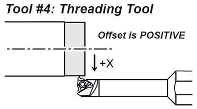
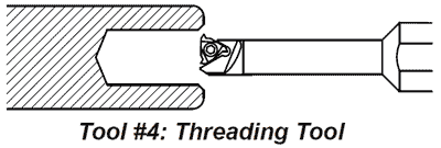
If you are using a finished part, touch off on the known inner diameter. The offset in this case is minus, so press ‘T’ to start the offset process; then ‘4’ for tool 4, then enter the ID as a minus.