 The Oregon Coast to show picture; click anywhere else (Apple IOS: refresh page) to hide picture.
NOTE: Click on brown textThe Oregon Coast to show picture; click anywhere else (Apple IOS: refresh page) to hide picture.
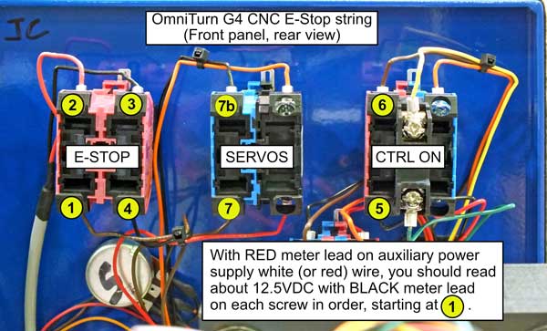
If the servos are not coming on, the most common reason is a bad Emergency stop contact, either in the control E-stop button or the E-stop on the Operator's Station.
You will need an ohmmeter to perform two quick tests of the entire e-stop string. If no ohmmeter or voltmeter available go to "Test Using Paper Clip Jumper", below.
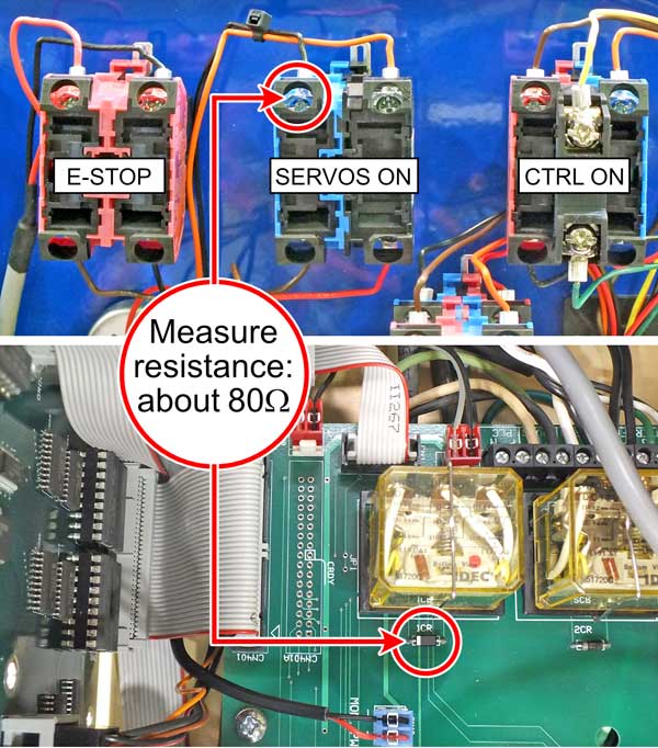
Test 1: With the power off, make sure the E-stop buttons are not pushed in and measure the resistance from the striped end of the diode next to 1CR to the black wire on the top of the blue contact block on the Servos On switch. This should be about 80 ohms. This measures through the 1CR relay coil and the E-stop string to the Servos On switch.
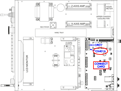
If the ommeter registers open circuit, could be issue with ribbon cable between CN1 on Connect Card and CN1 on Front Panel Connect Card, or with 1CR, or with front panel connector CNFP4. Refer to schematic.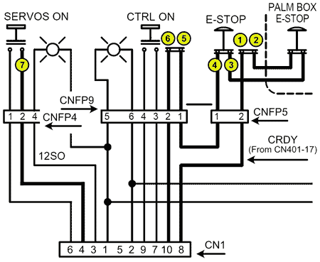
CN1, CNFP4, CNFP5, and CNFP9
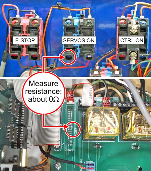
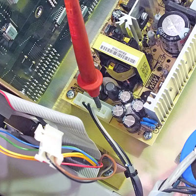
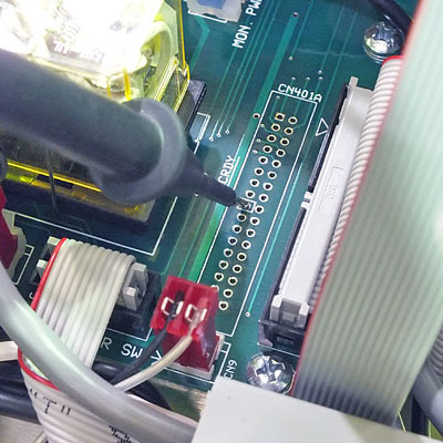
Test 2: With the power off, make sure the E-stop buttons are not pushed in and measure the resistance from the CRDY test point in the middle of CN401A to the brown wire on the bottom of the blue contact block on the Servos On switch. This should be close to 0, say less than 5 ohms. This measures through the entire e-stop string to the bottom of Servos On switch.
If the ommeter registers open circuit, one of the contacts in E-Stop or Control On switch could be bad. Scroll down to voltage tests below.
You will need a voltmeter set to DC volts. If no voltmeter, go to "Test Using Paper Clip Jumper", below.
Turn the control on: stop at the screen that shows the "Servos off or external halt.." message.
To check the ribbon cable, turn off the CNC and unplug ribbon cable 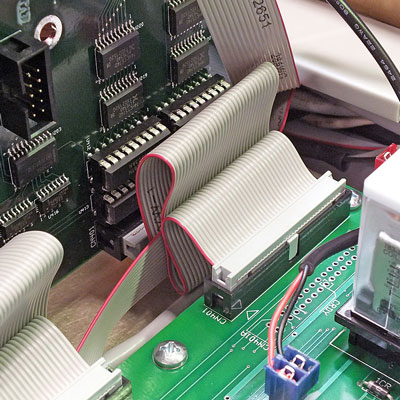
CB401 Ribbon Cable between 5AX and Connect Card
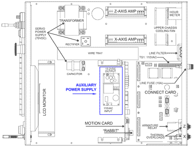
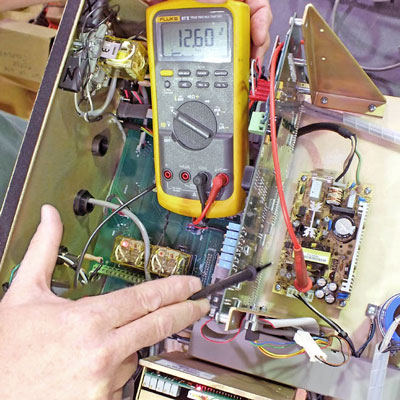
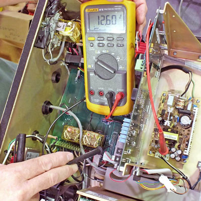
between CN401 on 5AX card and connect card. Examine the connectors to insure the ribbon is securely in place. Replug the ribbon cable, power up the CNC and see if you can turn on the servos. If not, recheck the voltage at CN401-17 as above: (RED meter lead on auxiliary power supply
RED Meter Lead on Auxiliary Power Supply
and BLACK meter lead at CN401-17).
Meter lead at CN401 CRDY.
If still not 12.5VDC, you will need to replace the driver IC U417.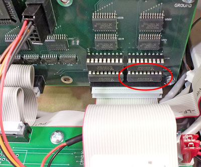
Driver IC U417
To replace U417, unplug the power cord for the control, remove the screws that hold the triangular brackets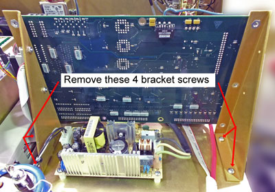
5AX Mounting Brackets
to the chassis, and tilt the card back to get access. Remove U417 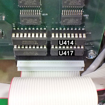
5AX Driver IC's U414 (spare) and U417
(the lower right IC) and set it aside, then remove U414 and plug it in to U417’s socket.
When removing the IC's from their sockets, be careful not to bend the leads- work them out gradually by slipping a small screwdriver or similar tool under one end, then the other. When plugging them into their sockets make sure that none of the leads get bent.
To check those contacts, jumper the top two terminals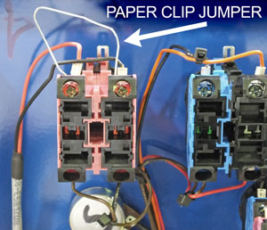
Jumper top terminals on E-Stop Switch
on the Control's Emergency stop button. (Set control power off before connecting jumper) If the servos will turn on after you do that, the problem is in the Operator's Station. Replace the OpSta E-Stop switch p/n 998-12-104).
If they still won’t come on, move the jumper to the bottom two terminals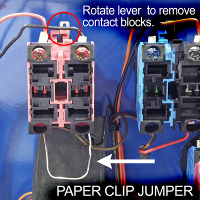
Jumper bottom terminals on E-Stop Switch. on the E-stop switch. (Set control power off before connecting jumper). Remove contact blocks from operator to make it easier. If the servos will turn on with jumper on bottom terminals, replace the Front Panel E-Stop switch p/n 995-12-103). Remove bottom jumper.
! DO NOT RUN THE MACHINE WITH JUMPER ON TERMINALS OF E-STOP SWITCH! !
Remove this jumper after testing for servos on! With this jumper you have no E-Stop.
If the servos won’t come on with jumper on bottom of E-stop switch, the problem is not in the E-stop switches. Use the paper clip to jumper between #7 and #7b on Servos ON switch. If that turns on the servos, replace the Servos ON switch (p/n 995-12-102). If that doesn't work, you will need voltmeter to troubleshoot. Remove all jumpers before proceeding.