OmniTurn   CNC Lathes Made in Oregon
 Fast... Precise... Affordable...HomeContact

The World’s Most Cost-Effective Turning Machines

Quickly Troubleshoot Servo Errors (G3 CNC)

If your OmniTurn occasionally throws a servo error, especially between tool calls, one of the servo amplifiers may need to be readjusted. This page describes that procedure.

"Servos Off" Screen appears on the display:

Image of G3 Jog Screen with Servo Error Prompt

The servos will turn off for two reasons: If the tooling plate is not where the computer expects it to be, or if an external fault occurs.

An external fault can be be caused by opening an interlocked door, by an auto-loader that has faulted, or by an engaged E-stop switch.

The tooling plate may not be where the computer expects it to be if it's bogged down in a heavy cut, or if G95 generates too high a feedrate, or if the servo amp balance is off.


Troubleshooting Steps

First, determine when the servo error occurs:

If the servo error occurs at a tool call, you may need to adjust the servo amplifier.

To quickly check if adjustment is necessary, turn on the servos, and in Jog mode press Ctrl-E (press and hold the Ctrl key, then press the E key: The Following Error screen will appear.

Image of G3 Jog Screen with Following Error Box

Both X and Z should show Following Error between -1 and +1.

Press the 2 key (Medium Jog), and jog the slide back and forth in each axis. The Following Error should be between 95 and 105 while jogging.

If the numbers at rest are not 0 ±1, you must readjust the servo amplifier balance and the motion card zero. If the numbers while jogging are not 100 ±5, you must readjust the servo amplifier signal gain and tach.


Servo Amplifier and Motion Card (MC2 Card) Location

For reference, the location of the servo amplifiers and motion card is shown below:

Image of G3 Servo Amplifier and Motion Card Location

Tools Requred for Adjustments:

  • A digital voltmeter (DMM or DVM)
  • Fine tipped probes, or paper clips
  • Jeweler's common screwdriver or trim-pot adjusting tool

Set Following Error to Zero at Rest:

NOTE: This procedure is different from what is published in the G3 manual.
Setting following error to zero is a two-part process (leave servos on for both steps):
  1. Balance the servo amplifier
  2. Zero the motion card

1. Balance the servo amplifier:

Image of G3 Servo Amplifier Adjustment Pots

Servo Amplifier Balance Adjustment:

Put probes of DVM between Pins 4 & 5 on servo amp signal connector. If the probe-tips are too large, cut pieces of paper clip and insert into connector holes to make contact.

First, turn the Balance pot CW two turns, then back CCW two turns, to clean the contacts. Then, adjust the Balance Pot on Servo Amplifier for 0V ±0.005V

G3 CNC's shipped prior to 2000 had AMC servo amplifiers (black in color). If you have those amps, adjust Test/Offset pot for ±0.005V.


2. Zero the motion card:

Image of G3 Motion Card Adjustment Pots

Motion Card Zero Adjustment:

On the motion card, turn the X and Z zero pots CW two turns, then back CCW two turns, to clean the contacts. Then adjust the X and Z pots until the following error is 0

Note that ±1 is acceptable; the numbers may alternate between 0 and 1.


Set Following Error to 100 at Jog 2:

Image of G3 Servo Amplifier Adjustment Pots

With following error screen displayed (Ctrl-E), select Jog-2.

Turn the Signal Gain and Tach pots CW two turns, then back CCW two turns, to clean the contacts.

Adjust the Signal Gain pot while jogging; adjust for 150 counts ±5 at the X and Z locations.
Next, adjust the Tach pot while jogging; adjust for 100 ±5 counts at the X and Z locations.

It doesn’t matter which direction you jog; the polarity will change, but the numbers will be effective.

G3 CNC's shipped prior to 2000 had AMC servo amplifiers (black in color). If you have those amps, adjust Ref In Gain pot for 100 counts ±5.


Servo Error Occurs in a Cut

If the servo error occurs in a cut, review the feeds and speeds specified for your material and compare with your program. The OmniTurn can push a tool with more than 750 pounds of force for a short time.

If you're drilling 3/8" or larger into steel, or taking cuts on a 2" or larger diameter part held in a chuck, the tool could bog down in the cut.

If you've made the parts before without issue, you may have chip buildup under the chip shields, or there may be an issue with the ballscrew.

Remove the chip shields and inspect the area.

If the error is in the Z axis you could try pushing the slide back and forth with servos off. It should move, not easily, but smoothly the whole length of travel.

If the error is in X axis on a GT, the slide brake must be disengaged to allow the slide to move.

To disengage the slide brake:

Send X home (send Z home also, to avoid possible crash), then turn off the servos. Find the slide-brake air solenoid, and manually engage it with a small hex wrench or ballpoint pen. The manual engage button is on the bottom, in the center of the black coil housing. You can see one on the top of the collet clamp solenoid, for reference. When you press the engage button, the slide should slowly fall to the extents of its travel.

If you've made the parts before with no issue, and you suspect binding based on the simple push (Z) or fall (X) test, then you should remove the motor and check for binding again.

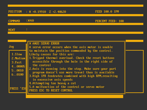
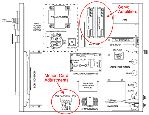
NOTE: If the servo error occurs in a cut, you may have to reset the thermal overload on the back of the CNC. You may also have to set servos off for two minutes to reset the servo amplifier.