Component Locations
The illustration below shows the location of the X and Z axis servo motor components.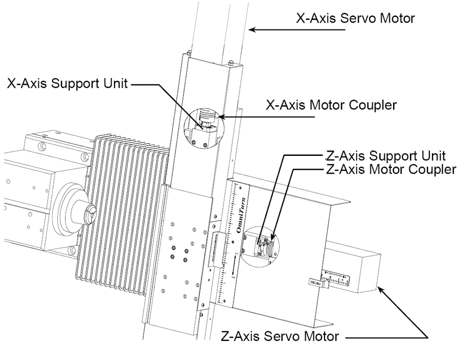
To remove Servo Motor and Coupler
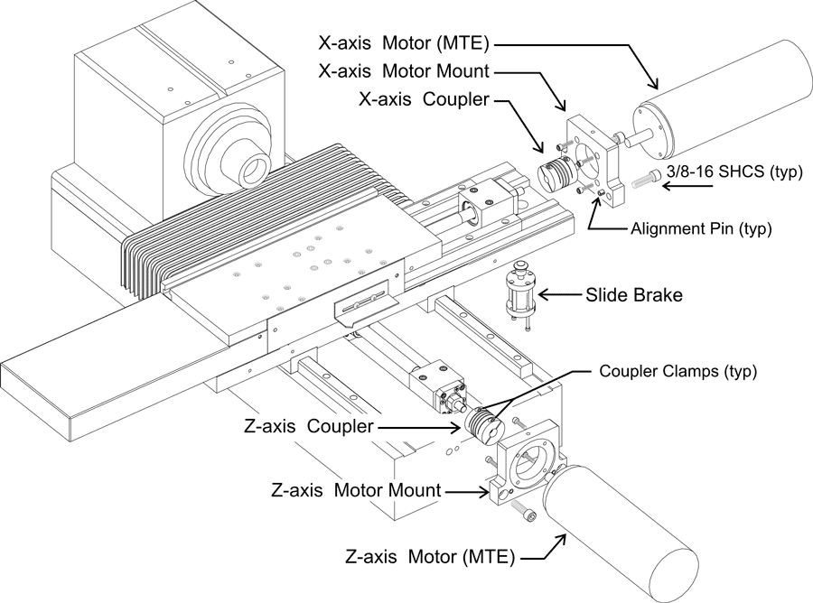
The drawing below shows axis motor assemblies exploded.
If only the coupler is being replaced, don't remove motor mount from axis motor.
- Remove sheetmetal.
- Loosen coupler clamps.
- Remove (2) 3/8-16 SHCS.
- Remove motor and motor mount. (Held by alignment pins).
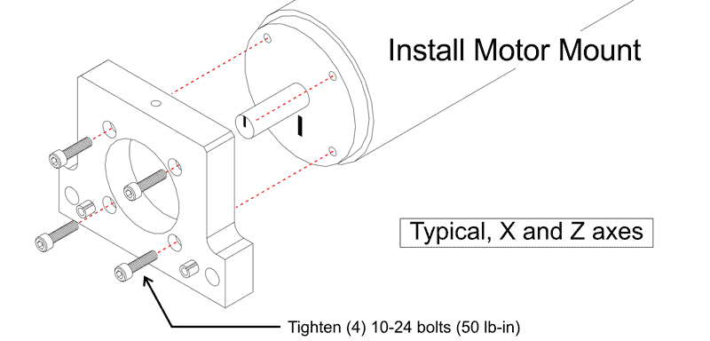
- To remove motor from motor mount, remove (4) 10-24 SHCS.
To Remove Support Unit (Thrust Bearing)
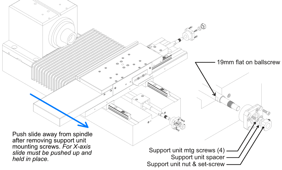
- Remove four socket screws holding support unit to block.
- Push slide in z-axis to expose flat on ballscrew.
- Loosen support unit nut set-screw.
- Loosen support unit nut using1/2”and 19mm wrenches.
To Replace Support Unit (Thrust Bearing)
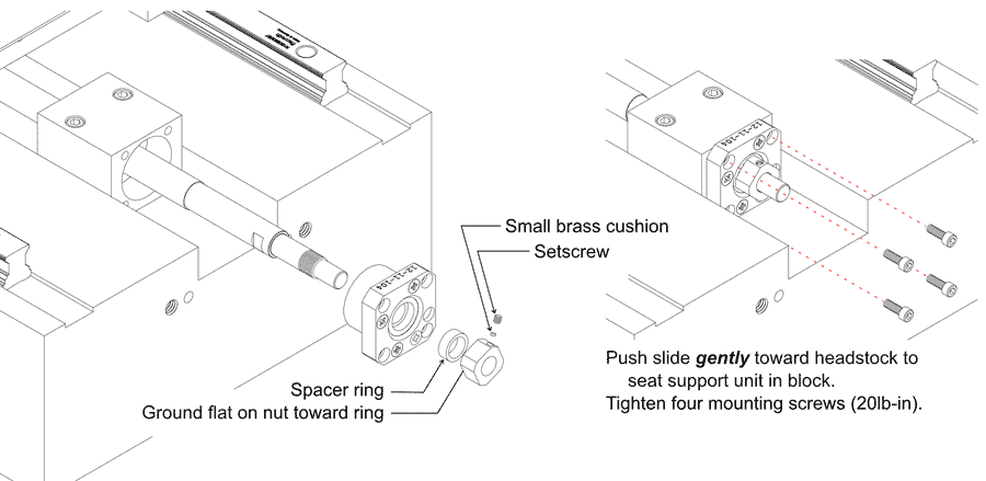
- Slip support unit onto ballscrew.
- Slide spacer ring onto ballscrew.
- Tighten nut using1/2”and 19mm wrenches.
NOTE: ground flat on nut goes against ring. - Install small brass cushion.
- Secure nut with setscrew (not too tight).
- Push slide gently toward headstock to seat support unit in block.
- Tighten four mounting screws (20 lb-in).
To Replace Servo Motor and Coupler
- On Z-Axis, pull the slide all the way away from the spindle, against the Belleville stack.
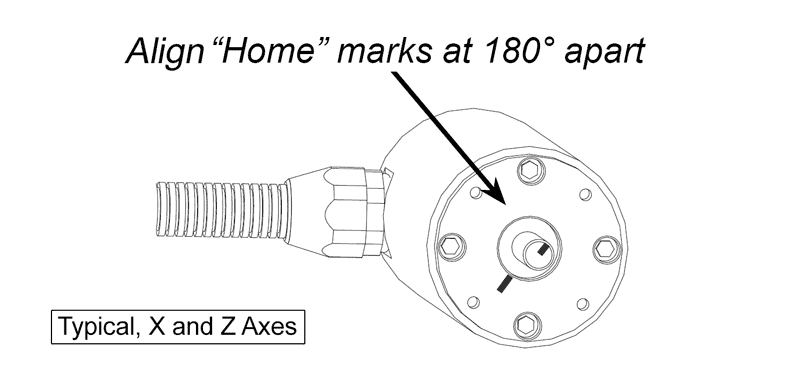
On X-Axis, let the slide go all the way down, against the Belleville stack. - Notice the mark on the end of the motor shaft and another on the face of the motor. These marks are aligned when the motor is at “home”. Turn the motor shaft so that the marks are 180° apart; that is 1/2 turn. This provides about 0.100” clearance past home.
- Attach the motor to motor mount: tighten (4) 10-24 SHCS to 50 lb-in).
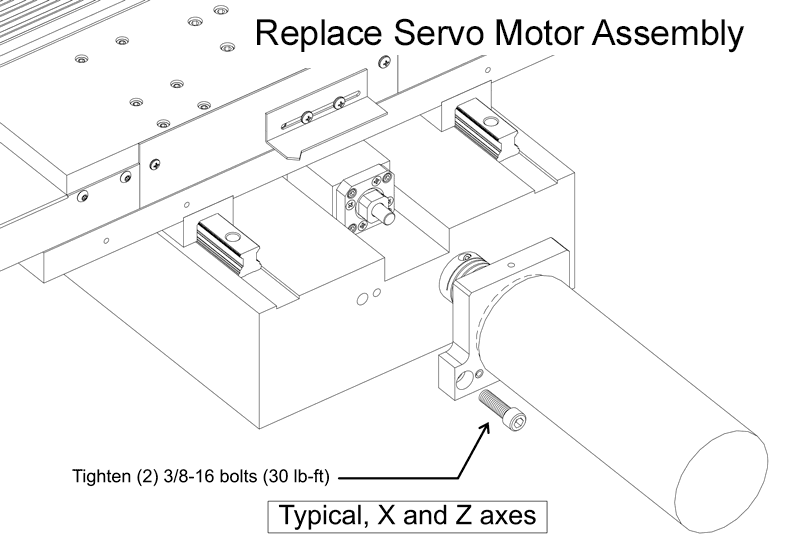
- Attach mount to the base, slipping the shaft into the coupler. Don’t let the motor shaft turn much off its 180° setting.
- Attach the motor mount to the machine: tighten (2) 3/8-16 SHCS to 30 lb-ft.
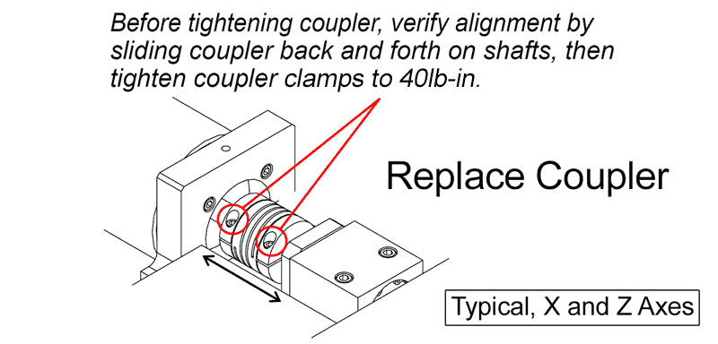
- Check alignment by sliding coupler back and forth on motor and ballscrew shafts; tighten the coupler clamps to 40lb-in.
- On X-Axis, replace slide brake.
- Install all sheet metal.
- After re-assembly, jog the axis toward home, and verify that the scale pointer will go just slightly past “0”; jog back inside of “0”, then establish Home as usual.
If the pointer is not at ”0”, loosen it and move it as required. - Re-set all tools before running!
Scroll down for step-by step instructions with illustrations.
- Align Home Marks at 180°
- Reinstall Motor Mount
- Reinstall Motor Assembly
- Verify Coupler Alignment and Tighten Clamps
- On X-Axis, replace slide brake.
- Install all sheet metal.
- After re-assembly, jog the axis toward home, and verify that the scale pointer will go just slightly past “0”; jog back inside of “0”, then establish Home as usual.
If the pointer is not at ”0”, loosen it and move it as required. - Re-set all tools before running!