Overview
This document has illustrations and instructions to assist in the replacement of the X-axis ballscrew on OmniTurn slides, either attachments or Gt’s. The illustrations use GT slide but are applicable for attachments as well.
IMPORTANT NOTE: Ballscrews are shipped full length for 12” X-axis travel. Ballscrews for early 10” X-axis must be cut to length using an abrasive saw.
- Remove sheetmetal
- Remove servo motor
- Remove support unit (thrust bearing)
- Remove tooling plate (table) with ballscrew
- Remove & replace ballscrew on tooling plate
- Replace tooling plate and ballscrew
- Replace support unit
- Tighten ballnut screws with table at home
- Replace servo motor
- Replace sheetmetal
Order of Operations:
Special Tool
5/32 hex wrench 14” long (tighten ballnut screws)
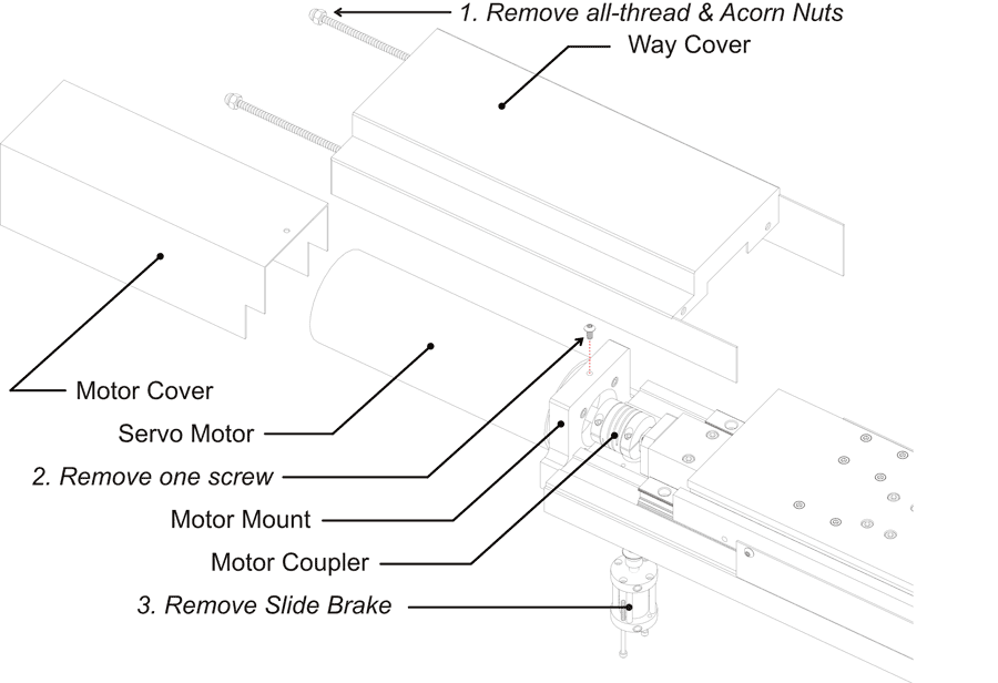
Remove X-Axis Sheet Metal: (Current)
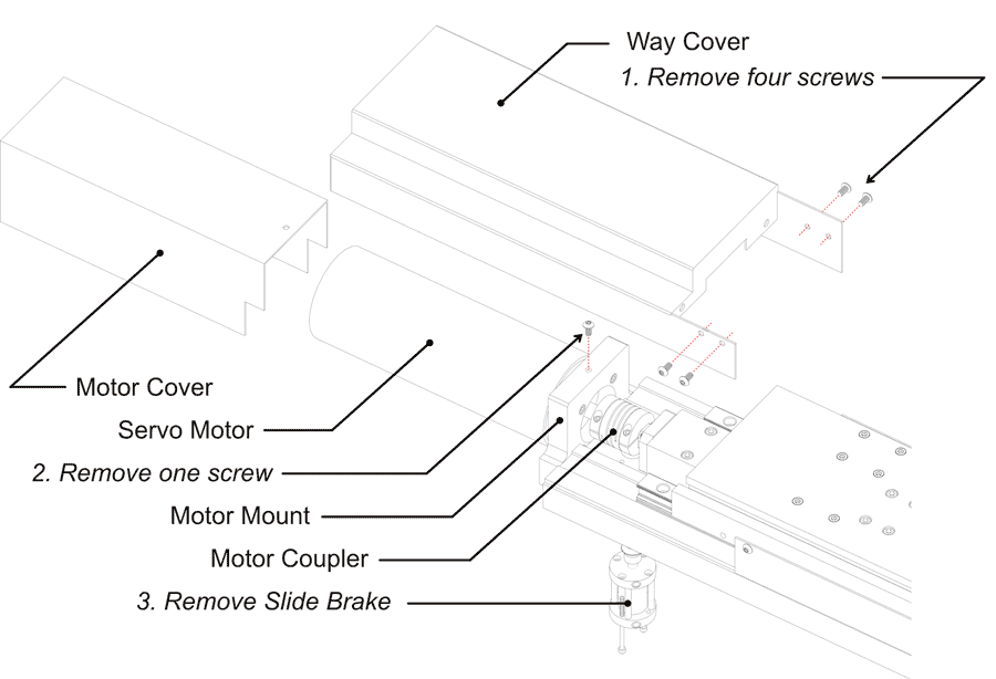
To remove X-Axis Sheet Metal: (Old-style)
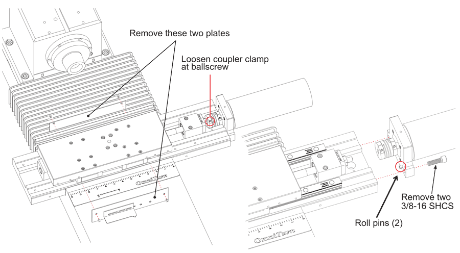
Remove Servo Motor
- Remove sheet metal plates each side of table.
- Loosen coupler clamp at ballscrew end.
- Remove slide brake if you haven’t already done so.
- Remove two 3/8-16 SHCS that hold motor mount to base.
- Roll-pins align motor to ballscrew; jiggle as required to remove assembly.
Remove Support Unit (Thrust Bearing)
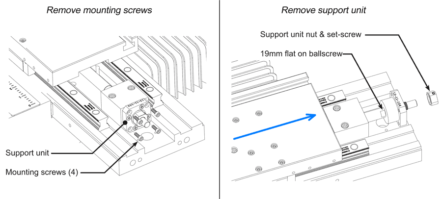
- Remove four socket screws holding support unit to block.
- Push slide in x-axis to expose flat on ballscrew.
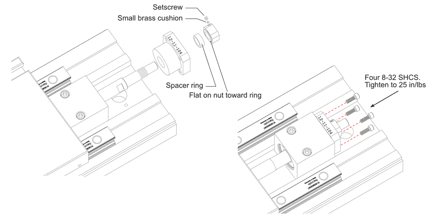
- Loosen support unit nut set-screw.
- Loosen support unit nut using 1/2”and 19mm wrenches.
After removing support unit mounting screws, push slide up to reveal 19mm flat on ballscrew.
Loosen set-screw in support unit nut, then move support unit nut using 19mm and 1/2" wrenches.
Note: there is a tiny brass cushion under the set screw. The new support unit has a replacement.
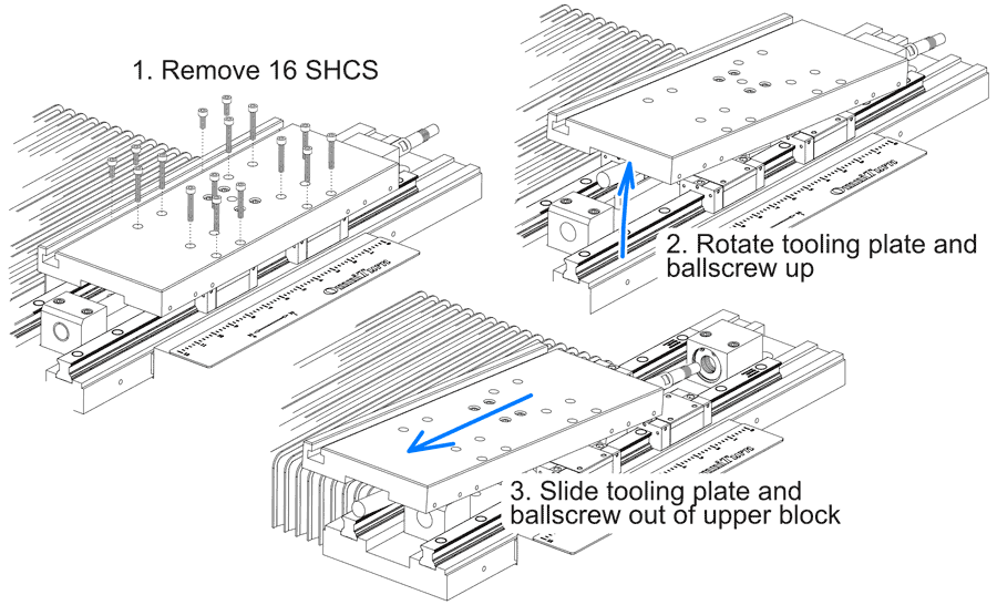
Remove Tooling Plate with Ballscrew
- Remove 16 socket screws holding tooling plate to trucks.
- Rotate table and ballscrew up, off trucks to clear lower block.
- Slide table and ballscrew out of upper block.
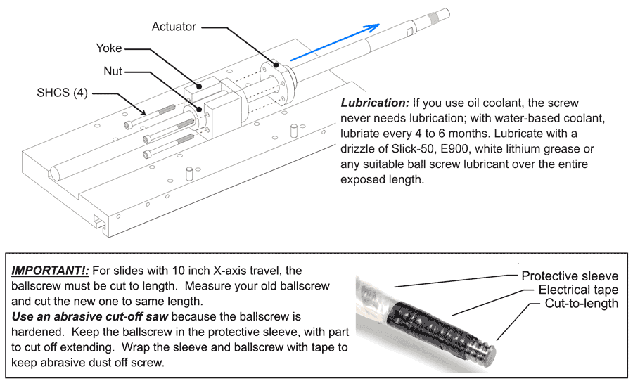
Remove & Replace Ballscrew
- Remove four socket screws holding actuator to yoke. Hand-tighten with new ballscrew; they will be tightened after alignment using 14” long 5/32 hex wrench.
- Slide actuator and ballscrew out of yoke.
- Replace ballscrew. (NEVER remove nut from new ballscrew; that will destroy the ballscrew.)
- Replace four socket screws. Hand tighten for now, they will be tightened after alignment.
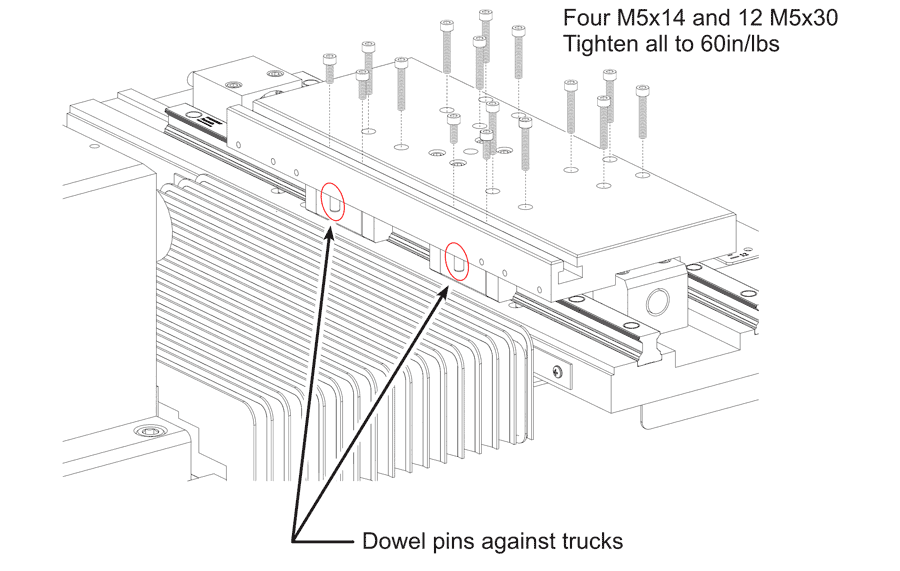
Replace Tooling Plate (Table)
- Slide ballscrew through support unit block and set table and ballscrew assembly onto trucks (Refer to Remove Tooling Plate), above.
- Line up holes in trucks and start screws. (The four screws that are below T-slot are M5x14; the other 12 are M5x30).
- As you tighten the screws, push the table plus Z to insure that the dowel pins are pressed against the two trucks as shown.
- Tighten all screws to 60 in/lbs.
Replace Support Unit (Thrust Bearing)
- Slide support unit onto ballscrew.
- Slide spacer ring onto ballscrew.
- Tighten nut using ½”and 19mm wrenches NOTE: Ground flat on nut goes against ring.
- Install small brass cushion.
- Secure nut with setscrew (not too tight).
- Slide table, ballscrew and support unit down to seat support unit in block.
- Tighten four 8-32 SHCS to 25 in/lbs.
Tighten Ball Nut Screws
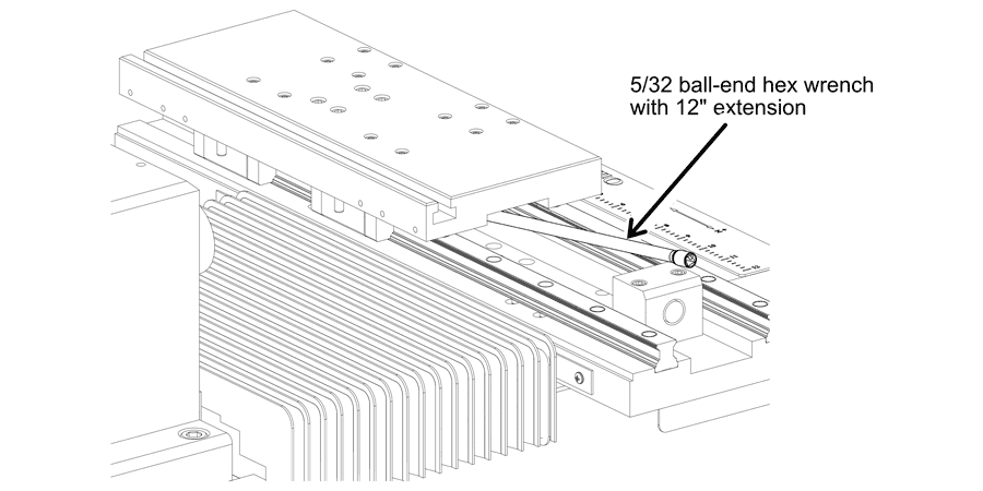
- Push table all the way to home; this will center the nut in the yoke.
- Use a 5/32 ball-end hex wrench on an extension to acces the screws.
- Tighten four 10-24 SHCS to 50 in/lbs.
Replace Servo Motor
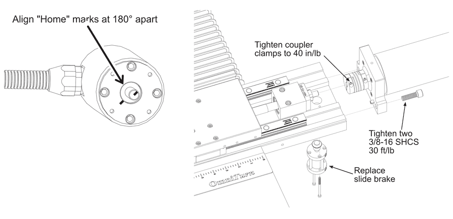
- Notice the mark on the end of the motor shaft and another on the face of the motor. These marks are aligned when the motor is at “home”. Turn the motor shaft so that the marks are 180°apart; that is 1/2 turn. This provides about 0.100” clearance past home.
- Install the motor with the table all the way down, against the soft stop.
- Attach the motor mount to the base, slipping the shaft into the coupler. Don’t let the shaft turn much. The motor mount has roll pins to insure proper alignment of motor shaft and ball screw.
- Tighten the motor mount to the machine before tightening the clamp on the coupler. Verify shaft alignment by loosening motor-side coupler clamp and sliding the coupler back and forth. Tighten both coupler clamps to 40 in/lb. Tighten motor mount screws to 30 ft/lb.
- Replace the slide brake.
- Replace all sheetmetal; review sheetmetal removal, above.
- After re-assembly, jog the axis toward home, and verify that the scale pointer will go just slightly past “0”; jog back to about 0.100, then establish Home as usual. If the pointer is not at ”0”, loosen it and move it as required.
- Re-set all tools before running.